This is a piece I completed a number of years back in school that I have wanted to write up retroactively...
Ever since my childhood realization that the process of welding was used to create objects of immense strength and scale, I had long aspired to acquire both a working knowledge of and manual skill in the process. Most welding performed today is some variant of electric arc welding, which is itself an inherently captivating intersection of electrical and physical phenomena. Arc welding is also particularly interesting in the way that it was so immensely advanced compared to the joining process it replaced in the early 20th century — hot rivets. If plastic injection molding was a zero to one event in consumer product manufacturing, arc welding would be the metal fabrication counterpart in industries such as shipbuilding and pipelines.
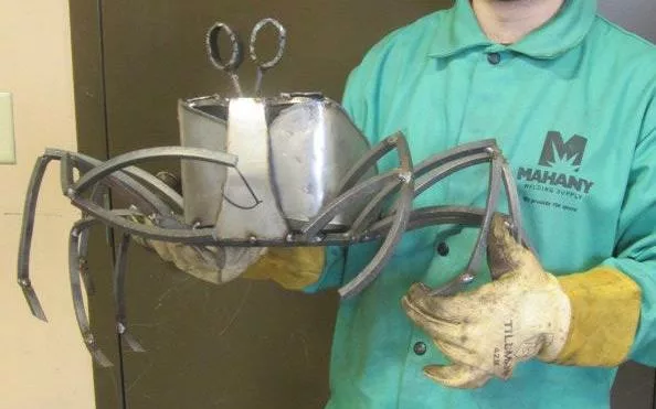
In this instance, the desire to acquire a skill (welding) was the dominate driver to expand the available scope of future projects. This is unlike the majority of my projects where execution simply necessitates skill acquisition along the way. I began by enrolling in a local MIG (Metal Inert Gas) welding class conveniently marketed specifically for those interested in “metal sculpture”. This is in contrast to a more traditional welding course for the commercial trades which imposes excessive focus on specific types of welds and weld evaluation criteria over a generalist this-to-that sensibility. The first output I created using this manual process took the form of a crab. This is a deviation from, but not such a distant relative of, my canonical folded crane form.
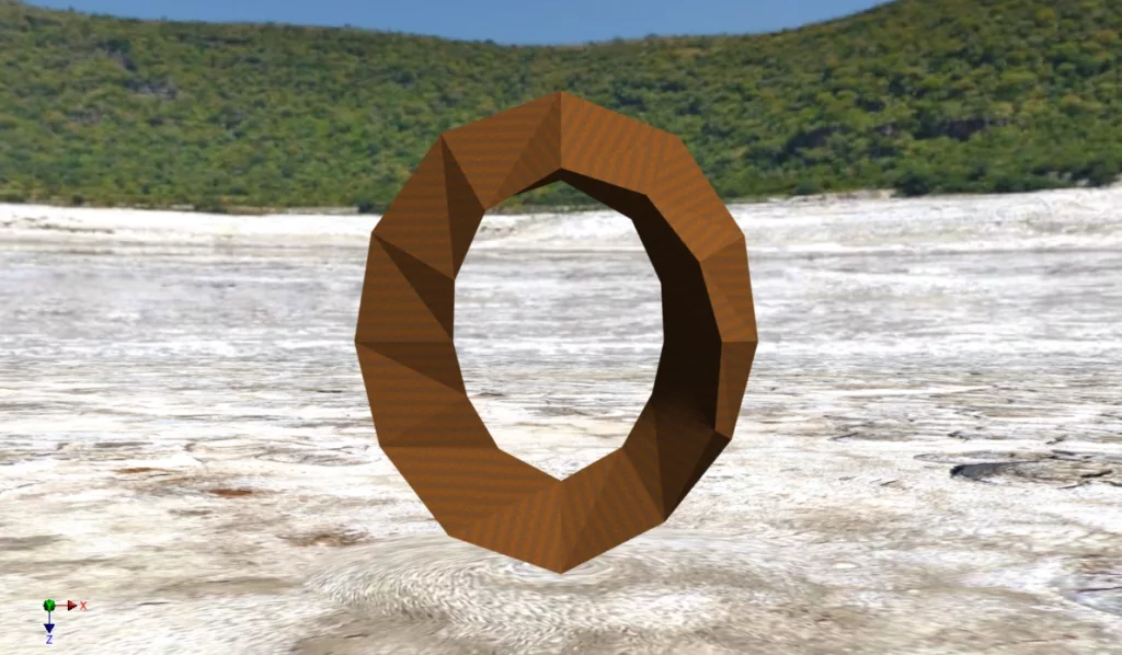
Once I actually understood the relatively low-stakes nature of MIG welding, dare I say the steel hot glue gun, the conceptual entry point for this piece was a Möbius strip. This is a classic and fascinating geometric form, but given that the conceptual form is a zero thickness surface, it does not easily lend itself to 3D fabrication. This is at least without both disproportionate surface thickness and complex curvatures. It is also a form that has been thoroughly explored in existing sculpture, and even in some engineering applications. Given these constraints, I settled on moving to what is strictly speaking a twisted triangular prism — and not a Möbius strip. However, I reserve the right to generate confusion given that the prism outer surface is a continuous traversal for non-integer rotations of twist.
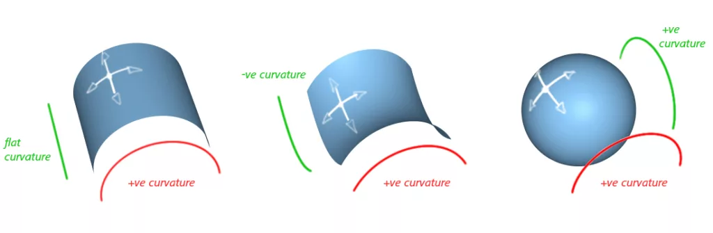
Going to the prism afforded the piece the volume, and therefore structural stability, I was seeking. This also enabled the use of far thinner sheet material which reduced weight and greatly improved the ease of handling and joining the material. However, this did not address the challenges of multi-axis bending. Below is an illustration of “single-axis” bends of sheet stock material as opposed the harrowing “multi-axis” bend.
The twisted prism actually exacerbated the concerns towards executing bends given the greater linear length and distinct sections that required bending. The prism also has the added the requirement to weld edges of surfaces together, creating a fitment constraint lacking in a classic strip. For a period, I considered learning the english wheel to go multi-axis, but after some trials concluded that this would be prohibitively complex for the scope of the piece. The solution was to tesselate the entire form.
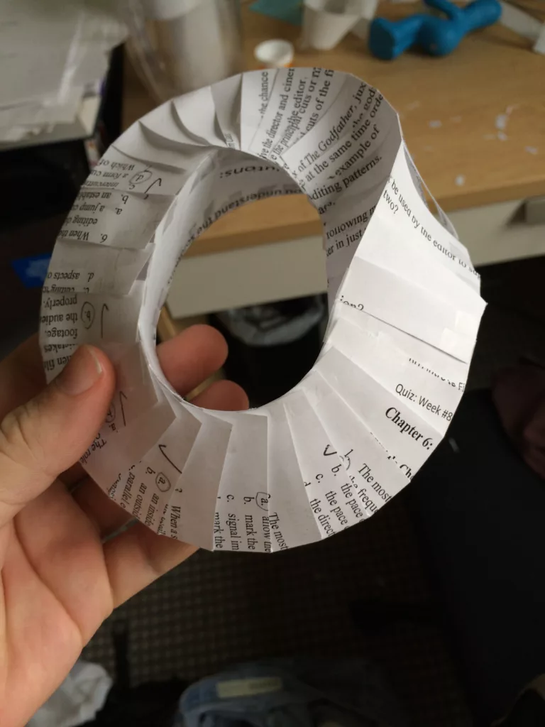
Since at this point I had a specific vision for the piece, I proceeded directly to a 3D CAD model instead of exploring more hand modeling with paper or clay. While I could have just 3D printed the digital model of the piece, I wanted to actually fabricate it out of sheet material in order to better understand the fitment, and evaluate whether it could be bent from a flat pattern or if it had to be a complete set of individual faces. It turns out there is an extremely adorable CAD software specifically suited to this task called Pepakura Designer. This allowed me to quickly print out and fold/glue a paper model.
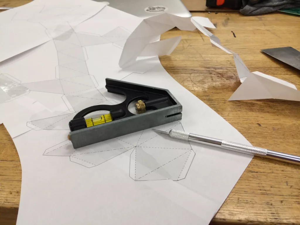
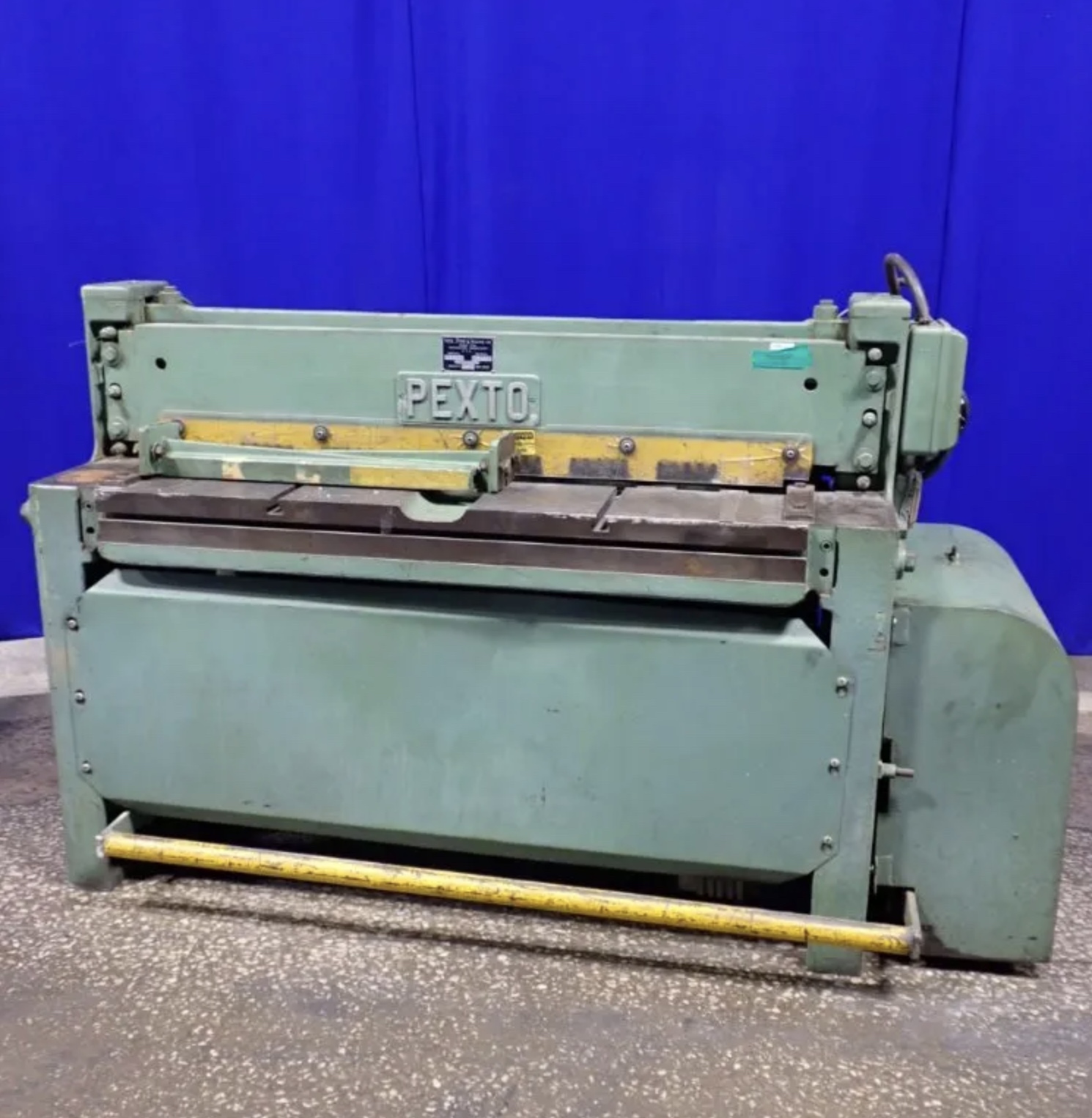
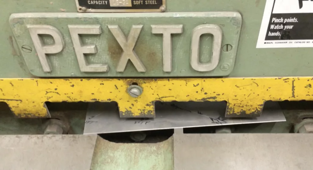
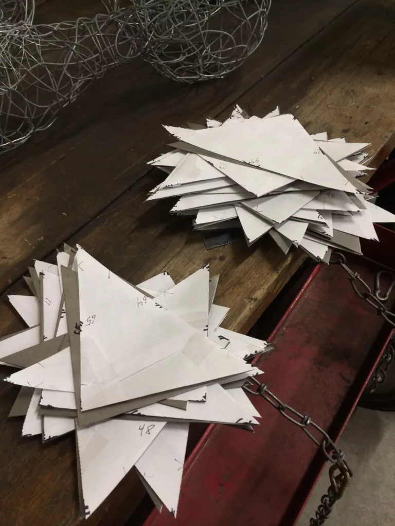
Constructing the paper model made it clear that attempting to cut subsections (perhaps 2-5 facets at a time) and bending them into final dimensions would be extremely difficult for fitment and bending brake clearance reasons. The studio I was working out of at school also happened to lack a proper press brake, but instead had available a wonderful fully automatic electric shear. Given this, I ended up printing a scaled-up version of the flat pattern on paper, and then using that as a template for the electric shear. This ended up being dramatically cheaper than laser or plasma cutting everything, and with the shear it really only took a couple hours to get through.
Although I was pretty comfortable with MIG welding, it turned out that the thin gauge material of the piece was better suited to the TIG (Tungsten Arc Welding) process. This actually made tacking the faces together extremely quick and clean. Assembling the facets went pretty smoothly until about half of the piece was joined. The fitment up to that point was precise enough that tacking didn’t even require any filler, the edge-to-edge contact simply fused with a quick tack.
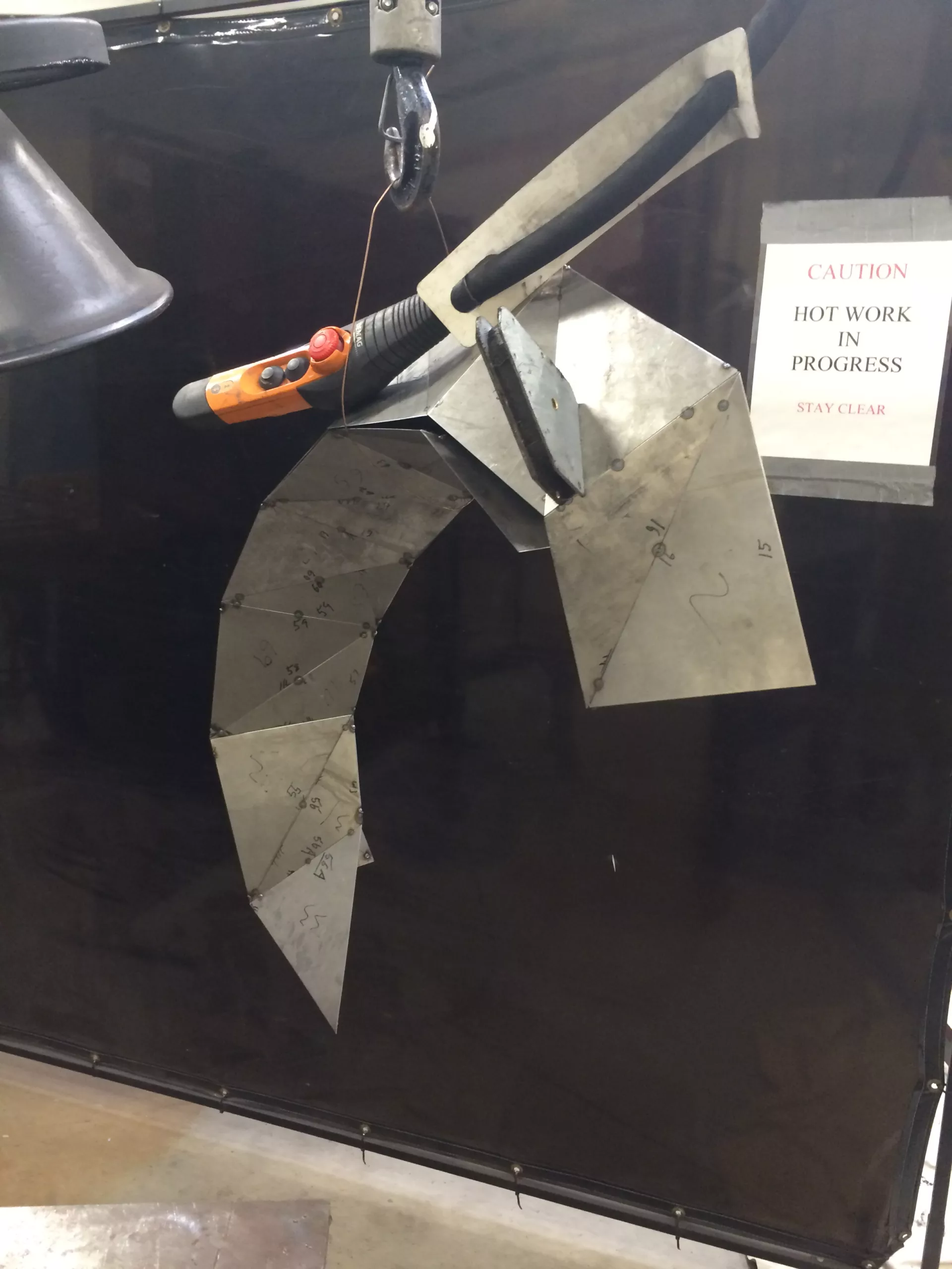
Getting the final edges aligned by incrementally tacking together the entire loop was clearly going to be troublesome, so I ended up assembling two subsections before finally merging them. The last few tacks definitely fought back a bit, and getting a closed edge required some racket straps and grinding out and re-tacking in a couple spots. Ultimately with some final convincing, all of the edges closed up to at most a 1mm gap or so. I didn’t bother fabricating any fixtures or jigs for this piece, and this was completely okay as it would have ultimately doubled the work. By the final tack I was extremely thankful I didn’t try to manual bending brake any of the faces as groups, as only a machine would have achieved the required arbitrary bend angle in any reasonable timeframe. That said, it is incredible to realize that even today, ULA still MANUALLY press-brakes their tank sections.
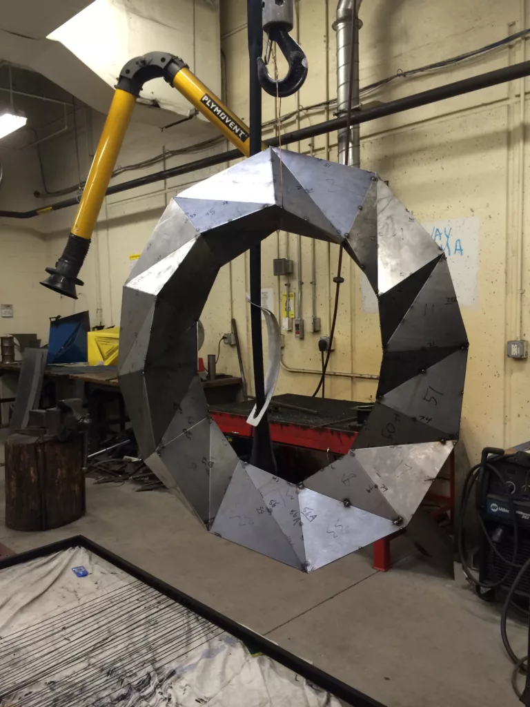
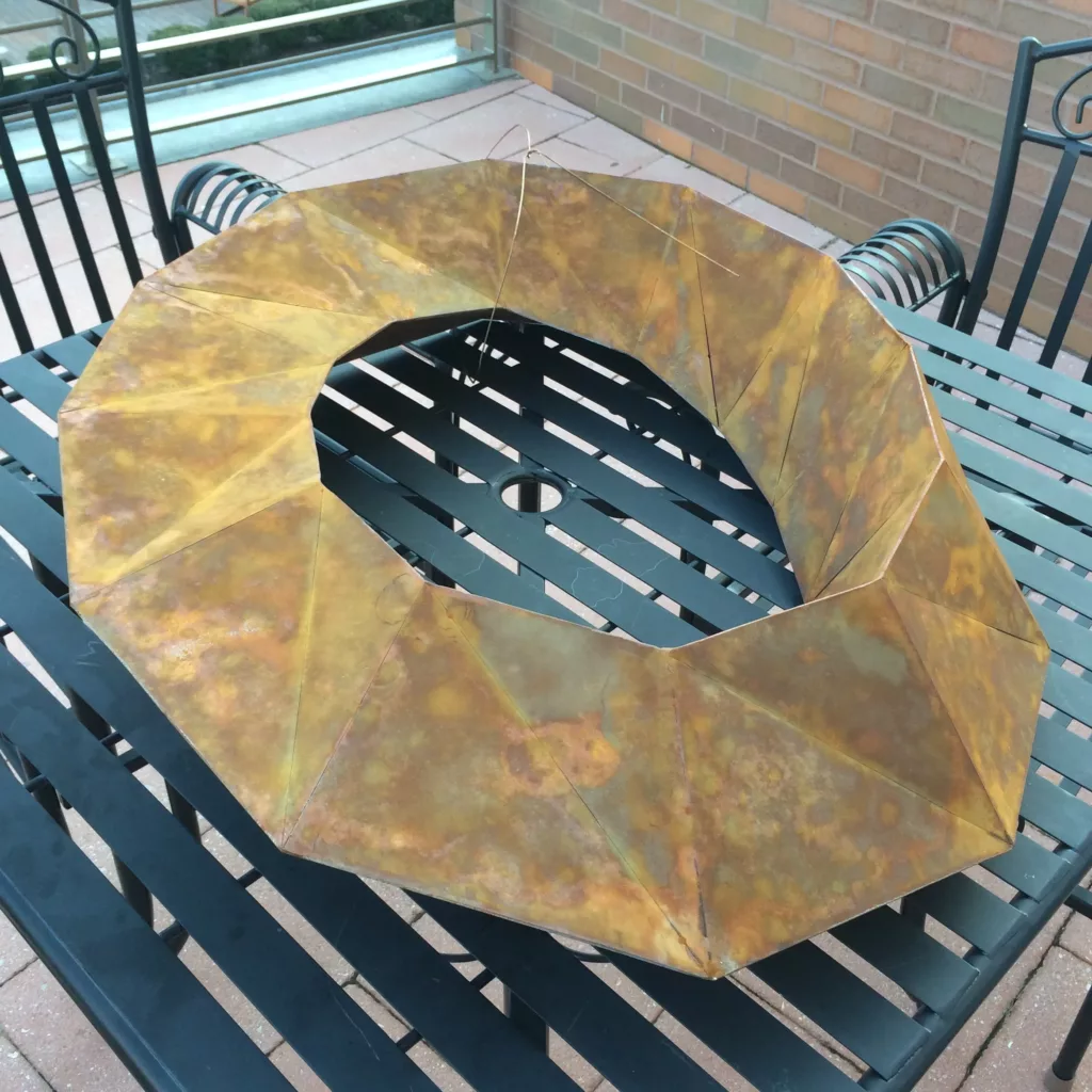
Finally, with the complete assembly fully tacked together, the piece was ready for final continuous welds. Final welds consisted of TIG welding all of the outer edges of the piece. It was pleasantly surprising how quick and easy this was relative to everything else. Most of the welds didn’t even require any TIG filler rod and was a simple fusion weld of the two sides of the workpiece directly together. There were definitely a few gap areas which required filler to prevent blowing out a hole.
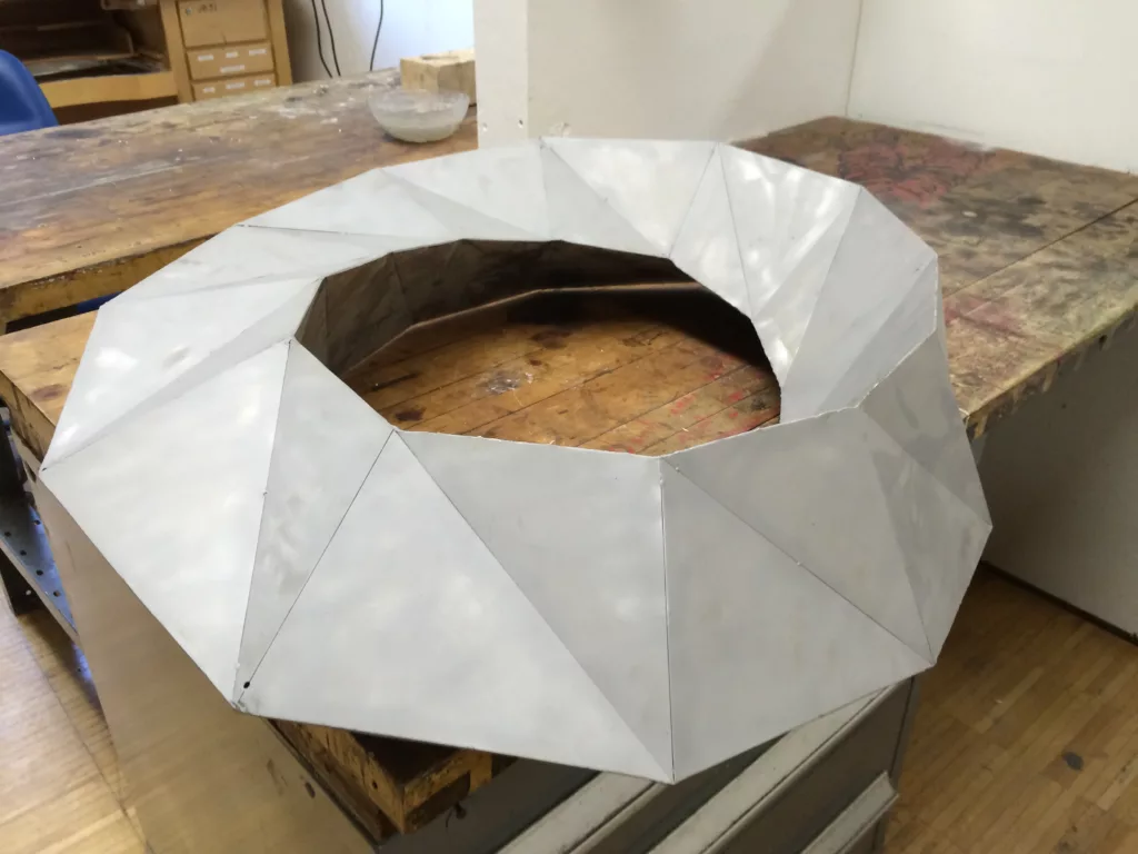
Final finishing consisted of media blasting, followed by a dilute nitric acid wash to achieve a consistent patina. Once the patina reached the desired quality, the piece was rinsed and dried followed by a spray of matte clear coat to fix the patina.